Tensile strength Testers are used to measure the tensile strength of paper and cardboard, such as pendulum type, torsion bar type, electric induction type, etc. Pendulum type Tensile Testing Machine is commonly used in CHINA, that is, Schopper Tensile Testing Machine.
(1) Schopper Tensile Testing Machine
①Structure and working principle
The Schopper Tensile Testing Machine is composed of a transmission transmission mechanism, a tensile strength measurement mechanism, and an elongation measurement mechanism. The transmission device drives the lower chuck to descend at a certain speed, and the tensile force is transmitted to the upper chuck upper chuck is driven by a chain to make the fan-shaped pendulum swing, and the brake claw slides on the arc-shaped rack until the sample breaks. When the fan-shaped pendulum is caught by the brake claw, the tensile strength value of the sample can be read directly on the scale by the rotation angle of the fan-shaped pendulum. The Schopper Tensile Testing Machine measures the tensile strength of paper based on the balance principle of a fan-shaped pendulum, so it is also called a pendulum-type Tensile Testing Machine. Its testing principle is shown in Figure 2-28.
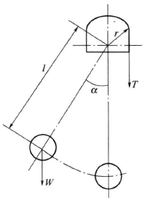
Figure 2-28 Principle of Schopper Tensile Testing Machine
② Calibration procedure
a. Adjust the instrument level and check the zero point.
b. Check the distance between the upper and lower clamps, the error should be less than 0.5mm.
c. Check the lowering speed of the upper chuck.
d. Check the scale value of the force dial, the error between the reading and the standard value of the weight should be less than 1%.
e. Calibrate the elongation scale.
f. Check the friction of the pendulum shaft.
g. Proofread pawl friction.
(2) Constant elongation tensile Tester
The constant elongation tensile Tester has two structural forms of single screw drive and double screw drive. Their working principles are the same, but each has its own strengths. The double-screw drive has a large load-bearing capacity, but requires synchronous transmission of the two lead-screws; while the single-screw drive has a small load-bearing capacity and a simple structure.
INSTRON double-screw multi-functional extensometer ﹑It is supported by double columns, the screw is installed in the column shell, and sealed with a leather sleeve, a crosshead is installed on the screw, and a sensor is installed on the crosshead. There is a single-board computer in the base of the main machine, which can control the whole machine and can automatically calibrate. The clamps are controlled by compressed air. The instrument is also equipped with a HP85-B microcomputer and a drawing and printing system. The output parameters include tensile strength, elongation, elongation, tensile energy absorption, stress-strain curve, etc. The instrument can also be used for fatigue test and compression test.
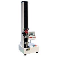
The single-screw electronic Tensile Testing Machine has the same working principle as the double-screw multi-functional tensile Tester, but it has a small load-bearing capacity and a simple structure. The main technical parameters include: the maximum load is 0-1000N, the elongation resolution is 0.1mm, the maximum tensile energy absorption is 1000J/m2, the maximum stroke is 450mm, and the stretching speed is 0-400mm/min. Before using the instrument, the load accuracy, tensile energy measurement error, and elongation measurement error should be calibrated, and the accuracy of the upper clamp's rising speed and .
(3) Horizontal Tensile Tester
①Structure and working principle
The main feature of the horizontal tensile Tester is that the direction of the tensile force is parallel to the horizontal direction. As shown in Figure 2-29, the two fixtures are placed along the horizontal direction. When the sample is placed in the fixture (the distance between the two fixtures It is 100mm or 180mm) to cover the luminescent tube. At this time, the pneumatic clamp is automatically connected and the sample is clamped, and then the running switch is automatically turned on. When the sample is broken, the clamp automatically returns to the initial state. The three displays respectively display the tensile strength, elongation, and tensile energy absorption values. The test speed is adjusted by a knob when it is broken, and there are two measurement selection range switches for tensile strength and elongation.
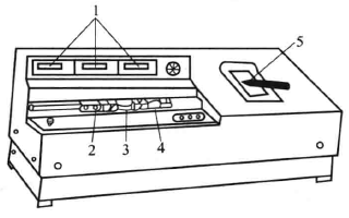
Horizontal Tensile Tester
1-digital display part; 2, 4- chuck; 3-sample; 5-recording part
② Calibration procedure
a. Display accuracy calibration.
b. Correction and adjustment of breaking time.
c. Elongation calibration, the error should be less than 0.05mm.
d. Check the accuracy of the displayed value of tensile energy absorption.
e. Check the reset accuracy.
(4) Electronic multifunctional testing machine
①Structure and working principle
The electronic multifunctional testing machine is mainly used for multiple physical performance tests such as tension, compression, bending, tearing and peeling of paper, plastic, rubber, composite materials etc. Figure 2-30 is the principle of the electronic multifunctional testing machine. Two lead screws with the same parameters are installed on both sides of the frame. When the two lead screws rotate synchronously, they drive the movable beam to move up and down. The sample is clamped on the chuck or other functional accessories. When the beam moves, the force acting on the sample is transmitted to the tensile (compression) sensor, and the sensor converts the force into a corresponding electrical signal and transmits it to the control unit and The function Recorder, the control unit displays the force value, and the function Recorder draws the force-deformation curve.
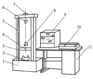
Electronic multifunctional testing machine
1-machine base; 2-bending test accessories; 3-bracket; 4-beam; 5-drive screw; 6-upper chuck; 7-force sensor; 8-lower chuck; Function Recorder; 11-workbench
②Main technical parameters
a. Rated load: 5kN.
b. Load display value error: less than ± 1%.
c. Speed adjustment range: 10~500mm/min.
d. Speed error: 2%.
e. Beam stroke: 1150mm.
f. Column spacing: 360mm.
③ Calibration procedure
a. Press the power button of the force measurement control unit, the power indicator light is on (if equipped with a printer, turn on its power), select the correct range, connect the sensor, warm up the instrument for half an hour, and the Recorder should be disconnected and set to zero.
b. Press the range selection key to the minimum range, adjust zero (the peak-tracking switch should be set to the tracking position), and then repeatedly adjust the measurement zero point in the minimum and maximum ranges.
c. Press the "calibration key" of the range and adjust the calibration knob to make the digital display value the calibration value provided by the manufacturer.
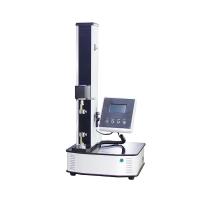
In addition, an electronic multifunctional testing machine can also be used. The main machine is a single-arm structure, controlled by a microcomputer, with a friendly interface, which can automatically analyze and process the test data, automatically calculate the test results, and can be saved and printed. According to the force range, it is divided into 100N, 200N, 500N, 1000N, 2000N, 5000N, and its main technical parameters are as follows.
a. Load display value error: within ±1% of the displayed value.
b. Effective stretching space: 800mm.
c. Test speed range: 0.1 ~ 500mm/ min.
d. Speed error: within ±1% of the indicated value.
e. Displacement accuracy: 0.01mm.