How to choose the right size disperser?

Dispersers are usually sized in terms of horsepower. However, there are diffusers that are very large in size but use relatively little horsepower. These are exceptions to the rule.
The horsepower of a disperser is related to the blade diameter and the expected load that the blade will produce at a given speed and drag. Resistance is a function of dispersion rheology as well as viscosity and density. However, horsepower increases disproportionately as blade diameter increases. For example, if a 12 diameter blade dissipates 20 horsepower in a non-Newtonian system
(Viscosity varies with shear), and doubling the blade diameter can increase horsepower requirements by a factor of five. This means that a 24 diameter blade of the same design, working in the same product, would require 100 horsepower. A bigger vane will also pump more, so it can work in a larger (maybe five times the volume) tank and produce more finished product
products of the same period. Horsepower requirements vs. blade diameter, tank diameter, batch size, rheology,
viscosity and density. Variations beyond the recommended operating parameters often result in reduced performance such as poor particle separation, prolonged dispersion times, and reduced finished product quality.
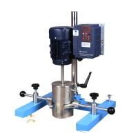
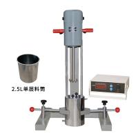
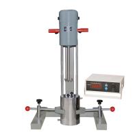
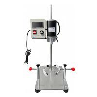
What are the different types of dispersers available?
Dispersers are available with single-speed, two-speed and variable speed mixing shafts. Some mount directly on top of the tank and are secured to operate with the blade only in the original mounting position . Other canister dispersers can raise and lower the blades a few feet without leaving the canister (for better control of the vortex). Another design, perhaps popular, places the diffuser on a floor-mounted hydraulic lift (similar to the ones gas stations use to lift cars up and down). The lift enables the operator to fully lift the blade out of the mixing vessel and change to another vessel. This technique uses small portable tanks (up to 500 gallons) that can be rolled off on wheels or picked up with a forklift. The larger stationary tank is usually located within the arc of rotation from the center of the elevator to the center of the mixing shaft. A bridge containing the mixing shaft at one end and the motor at the other then rotates from one tank to the next. Selecting an appropriate configuration of available designs is a combination of functional requirements and economic rationale.