The relative difference between the perforated roll and the applicator roll can be equal or slightly different. The applicator roll can run at the same or slightly lower surface speed than the web to create additional coating spread on the web. The perforated roll system is unique in that shear is eliminated throughout the fluid transfer process. This means that fluid materials can have reasonable shear sensitivity and swelling properties. The perforated roller coating system simulates the printing process, similar to rotary screen ink printing (see Figure 22.8). The main difference is that the perforated roll system receives a fluid supply that is synchronized with the speed of the machine, while the rotary screen printing process utilizes a drawdown blade mechanism located inside the screen cylinder. Rotary screen printing process speed is affected by ink viscosity. This means that highly viscous inks can limit machine speed.
In contrast, perforated roll systems with synchronous volumetric fluid supply are insensitive to viscosity changes. An important element is synchronized fluid metering for consistent and controlled coat weights applied over a wide range of machine speeds.
Manufacturers of curable silicones state that in order to achieve exceptional levels of mold release, higher viscosity materials are required. As mentioned earlier, traditional multi-roll coating systems perform better with fluids less than 1000cp. Perforated roll systems have been tested with coating viscosities up to 10,000 cp.
Varying the micron opening in the perforated roll applicator will allow higher viscosity materials to be processed (see Figure 22.9). For example, coatings of polyethylene resin emulsion adhesives with a viscosity of 5000 cp at a coating thickness of about 30 μm have been successfully applied without difficulty. Silicone products or other coating materials with higher viscosities (eg 10,000 cp) may require porous rolls with larger openings, depending on flow characteristics. Larger porous openings will minimize fluid back pressure and allow for consistent coat weights at various machine speeds.
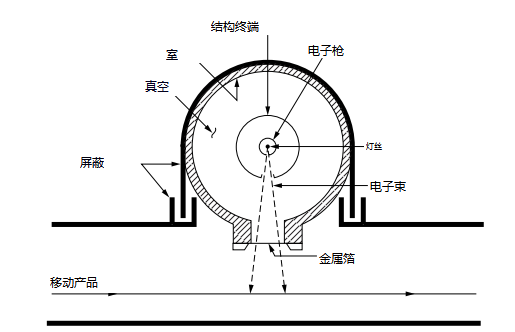
Figure 22.2 EB process.
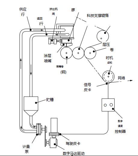
Figure 22.3 Roller coater with extrusion feed
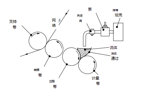
Figure 22.4 Transfer roller coater
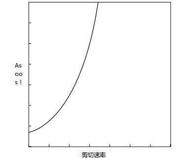
Figure 22.5 Viscosity vs. Shear Rate of an Expanding Fluid
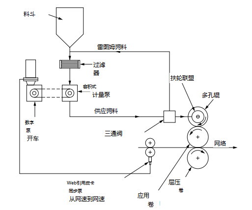
Figure 22.6 Perforated roll coater.
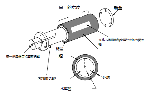
Figure 22.7 Schematic diagram of a porous volume
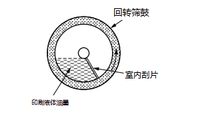
Figure 22.8 Rotary screen printing machine
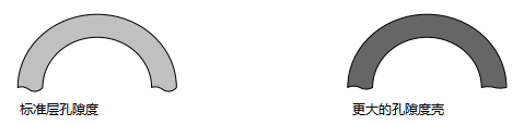
Figure 22.9 Porosity of Porous Roll Applicator
The porous roll surface can be sealed to print fluids in the pattern, as shown in Figure 22.10. This means that the special coating patterns required in flexible packaging products, business forms, envelopes, tapes and labels can use curable silicone coatings in the final conversion process, rather than using pre-silicone printed rolls.
The perforated roller system can also be configured to handle multiple coating materials within the same applicator. A cross-sectional view of the applicator (Figure 22.11) showing the different chambers that supply the various fluids. This feature allows the converter to apply different materials at the same time, but using the same applicator. Special tape products that require different release levels on the same roll can take advantage of this concept. For example, 25 g/25 mm of release agent can be applied to the left side of the sheet, while a 100 g coat of release agent can be applied in the center or adjacent to the same sheet. Products such as double-sided release-coated rolls used in transfer tapes can be easily coated using two separate perforated roll coating systems located on both sides of the roll as shown in Figure 22.12. Combined with UV or EB curing equipment, used to crosslink the coating to complete the final product.
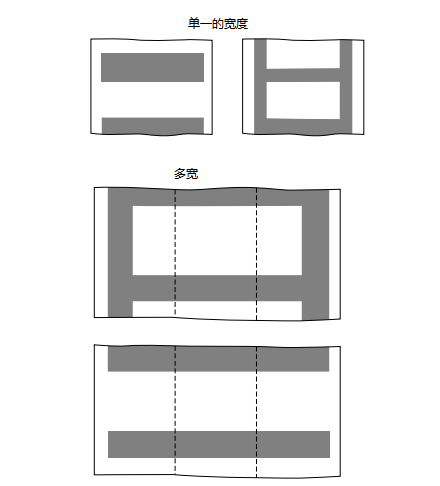
Figure 22.10 Pattern printing using a perforated roll.
The perforated roller system also allows high release levels such as 100, 200 and 400 g/25 mm to be obtained by using two-component silicone systems. This concept utilizes two perforated rollers that are in direct contact with a single rubberized applicator roller (Figure 22.13). Component A is supplied via perforated roll B. Part A represents the base silicone coating material, while Part B is the thinner. The purpose is to mix the thinner into the base silicone. The ratio of A to B determines the level of fluid release. The concept is experimental at this stage, but tests have shown that the two-component system is an alternative process for obtaining future "dial-in" version levels. The schematic diagram of the laboratory coating machine is shown in Figure 22.14, and the schematic diagrams of the production size units are shown in Figure 22.15 and Figure 22.16.
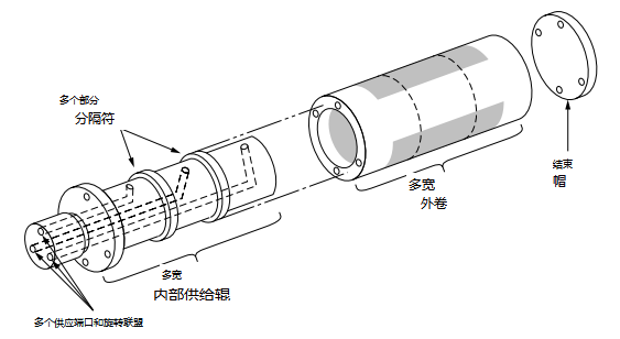
Figure 22.11 Cross-section of a perforated roller coater
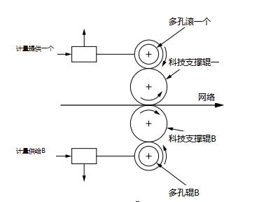
Figure 22.12 Two-sided coating with perforated roller
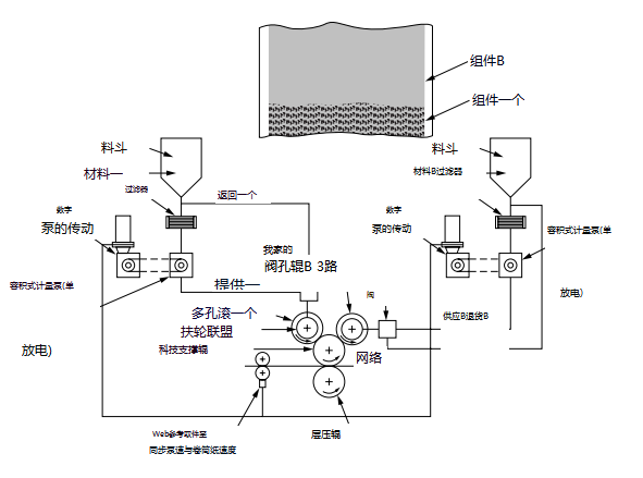
Figure 22.13 Application of two-component silicone system
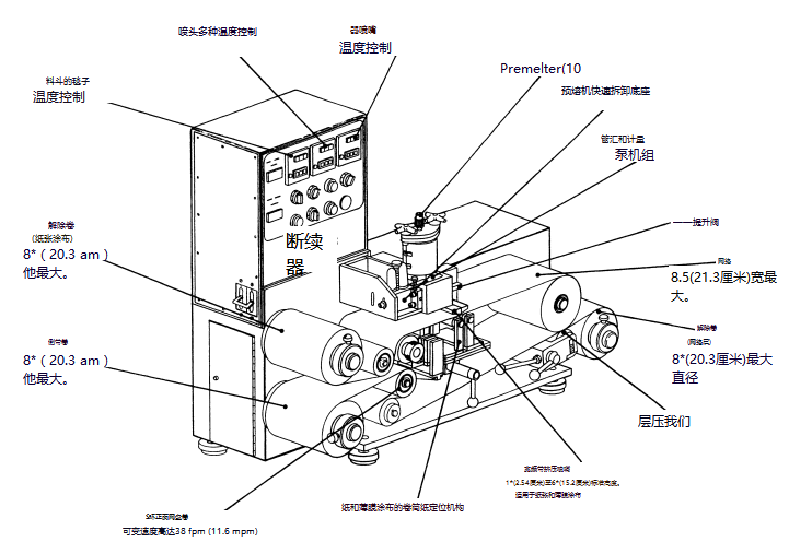
Figure 22.14 Schematic of a perforated roll laboratory coater
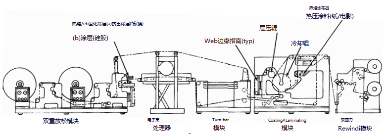
Figure 22.15 Coating line with perforated roller coater
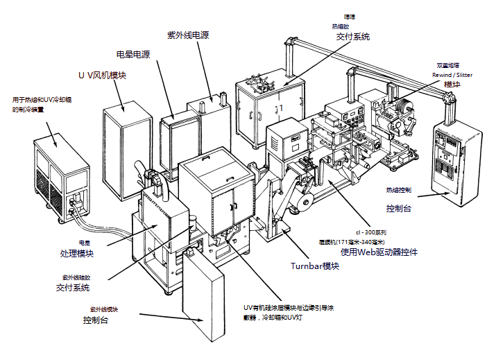
Figure 22.16 Label paper production line