verify
The importance of verification is self-evident
Calibration certificates do not guarantee accuracy throughout the calibration interval. Many factors can adversely affect the operation of a gauge, such as accidental damage or debris buildup. To prevent measurements with inaccurate gages, most standards require verification of accuracy and operation before each use, usually at the start of each work shift. After taking a large number of measurements, if the gage is dropped or suspected to be giving erroneous results, it should be rechecked. Contracting parties will usually reach a preliminary agreement on the details and frequency intervals for verifying gage accuracy.
What do you do during these time intervals? It depends on your existing quality system. When their gage is new, some owners simply measure a sample part and record the results. This sample is then saved and used to periodically check the operation and accuracy of the gage.
However, a better and generally accepted method of checking accuracy is to measure a calibration standard in a controlled environment using a written procedure. ASTM D7091 contains typical language for many standards:
"Accuracy Verification—Prior to use, the user should verify the calibration accuracy of each instrument using an appropriate coating thickness standard according to the manufacturer's instructions and, if necessary, correct any deficiencies found. Gages should be verified to ensure that they are within the intended range of use accuracy."
Calibration standards come in a variety of forms, depending on the instrument being validated. They need to be traceable to the national metrology agency and measure within the range of the gage—ideally, close to the expected range of measurement. The process for measuring them is described in a document called a calibration procedure, which some manufacturers publish or make available upon request.

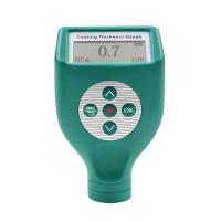
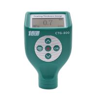
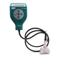
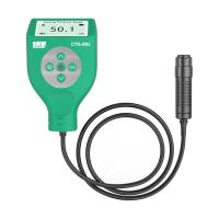
For coating Thickness Gauges, coating thickness standards are available as certified coated metal plates or plastic shims. Plates are usually more accurate and durable, but also more expensive. Type 1 (mechanical) coating Thickness Gauges cannot be verified with plastic shims.
The average of the series of readings should be within the combined tolerance of the gage and reference standard. To determine combined tolerances, the tolerances of the gage and standard cannot simply be added, but a "sum of squares" formula should be used. For example, if the reference standard has an accuracy of ±2% and the instrument has an accuracy of ±3%, the combined tolerance is ±3.6%, calculated as:

If the reading is outside the combined tolerance, there is a problem with the gage or reference standard. The gage or reference standard in question should be identified and all measurements made since the last accuracy check should be considered suspect.
tuning
For many inspection instruments, calibration and verification are sufficient to ensure that the instrument measures correctly. However, with coating Thickness Gauges, a third step is usually required: adjustment. This is because coating Thickness Gauges do not directly measure the thickness of the coating; instead, they measure the magnetic properties of the substrate. These properties weaken as the probe moves away from the substrate and are thus related to coating thickness.
However, there are other factors that can affect the magnetic properties of the substrate. These include:
Surface roughness (usually caused by sandblasting)
Geometry (curvature, edge effects)
Composition (metal alloy, magnetic properties, temperature)
Mass (thin metal)
Coating Thickness Gauges are usually calibrated at the factory to perform well on flat, smooth carbon steel. However, if adjusted, they can be accurately measured in applications with different surface roughness, geometry, composition or quality:
"3.1.2 adjustment—the physical act of matching (removing bias) the thickness reading of a gauge to that of a sample of known thickness in order to improve the accuracy of the gauge on a particular surface."
It is important to note that any adjustments only take into account the substrate roughness, geometry, composition and/or quality where the adjustments are made. If any of these factors change within a part or job, further adjustments are usually required. Some electronic instruments, such as the Defelsko PosiTector 6000 Advanced model, are capable of saving multiple calibration adjustments so that the user can select the appropriate adjustment for the application at hand.
It should also be noted that not all coating Thickness Gauges are created equal. For better guidance on how to adjust a particular instrument, consult the manufacturer or the instrument's user manual. The following overview is a guide for adjusting one of the common coating Thickness Gauges.
Adjust geometry, composition and mass
To determine if the instrument needs adjustment, check that the average of a series of readings on uncoated substrates is within the gauge tolerance at zero time. If the measurement is out of tolerance, the gage may need to be adjusted. This is usually as simple as offsetting all future measurements with errors encountered during the check measurements. Type II electronic gauges like the PosiTector 6000 often have a built-in "zero adjustment" function that automates the process. If subsequent measurement readings of the uncoated substrate are within the zero tolerance, the adjustment has been successfully performed. Type I mechanical tension gauges (such as PosiTest) have a non-linear scale, so the instrument itself should not be adjusted. instead,

For almost all applications, after a successful zero adjustment, the instrument will measure over its entire range. This can be verified by placing a shim on the uncoated substrate and ensuring that the gauge reading is within the combined tolerance of the shim and gauge. In rare cases where the gauge reading is within zero tolerance but is out of tolerance on the gasket, further adjustment may be required. For details, consult the manufacturer of the product manual.
Adjust Surface Roughness
While zeroing is usually sufficient to account for geometry, composition, and quality effects, zeroing should not be performed on blasted or rough surfaces. On these surfaces, the coating Thickness Gauge will measure to points between roughness peaks and valleys known as "magnetic planes." An adjustment is required since most standards and codes state that only the coating thickness at the surface profile peak is reported.
An acceptable procedure to ensure that the coating Thickness Gauge will measure the coating thickness above the "peak" of the surface profile is to adjust to the known thickness of a shim placed on the uncoated substrate. Shims sit on top of the peaks of a surface profile or other pattern and are a replacement for the coating film that will eventually be applied. Type II electronic gauges often have a built-in "1-point adjustment" feature to simplify the process.
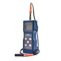
Because Type I mechanical pull gauges typically use large magnets rather than small probe tips to contact the surface, they are less affected by surface roughness. The user can simply perform a zero adjustment by taking a base metal reading (BMR) on an uncoated blasted substrate and subtracting this value from future coating thickness readings.