Understanding the basic theory behind slot die coatings cannot be overemphasized in terms of the importance of understanding how operating parameters and slot die geometry interact to produce a stable coating. High-quality coatings can only be obtained within a specific coating window, and moving outside this stable coating window will lead to the formation of defects—until the film will no longer be coated.
By understanding the source of defects in the coating film, it is possible to understand which process parameters and slot die geometry need to be changed to return to a stable coating area.
solution distribution
The distribution of solution through the slot-die manifold is determined by several competing processes that drive fluid motion and others that hinder it.
These can be categorized as:
The hydrodynamic pressure of the solution entering the manifold
Gravity helps push the solution down the slot die
Viscous loss
inertial acceleration of the fluid
The flow rate of the solution is determined by the pressure drop across a given portion. Therefore, in order to understand the flow of the solution through the manifold, it is necessary to calculate the pressure drop at various points and determine the flow of the solution. This can be done by computer simulation using finite element analysis, where the pressure drop for each individual element is calculated.
These pressure drops can be calculated using the following equations, where the pressure drop (dP) across a finite length manifold (dx) is determined by four different terms:
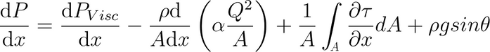
The first of these terms is viscous loss in a fluid. These may occur due to molecule-molecule interactions within the liquid itself and depend on how fast the solution is moving and the length of the solution transport. This term governs pressure drop at high viscosities and very high flow rates.
The second term is the inertial acceleration, density (rho), cross-sectional area (A) and velocity of the solution (d/dx) of the fluid as it enters the manifold section. The term in parentheses is a correction factor that accounts for the direction of solution flow relative to the direction of the cross section. This is important with sloped or curved manifolds, such as coat hanger or constant shear manifolds.
The third term concerns the shear force at the surface perpendicular to the solution flow. For elements close to the die wall, the stress tensor (tau) is related to the average velocity of the finite element. Viscous loss occurs when two adjacent regions have different flow velocities. Therefore, at the cavity walls, the stress tensor is high since the flow of the particles is zero at this interface.
pressure drop due to gravity. The term applies only to cavities where the manifold is at an angle, such as coat hanger and constant shear manifolds.
Land and Slot Flow
In lands and grooves, the groove thickness-to-length ratio is low enough that the lubrication approximation can be used to predict solution flow.
This results in the flow rate being given by the Pouiselle equation (shown below). At the boundary between the manifold and the tank, pressure and flow need to be continuous.

In fact, there may be a small pressure loss (due to the change in flow direction) during the transition between the manifold and the tank, resulting in viscous losses and inertial forces. This can occur at abrupt interfaces that can cause eddies in the solution flow. These can be reduced by using a manifold cross-section (e.g. a teardrop-shaped design) to smooth the change in flow direction when transitioning from the manifold to the tank.
The change in pressure can be given by the pressure difference between the manifold and the slot die outlet. Due to conservation of mass, if the flow is fixed by the metering system, the flow through the tank needs to remain constant. Thus, the pressure drop is regulated by the viscosity of the solution, the length of the plateau and the thickness of the channel.
The channel length of the slot die coater is difficult to adjust and requires re-milling of an entirely new head to achieve this. This makes it impractical to use tank length as a means of controlling the pressure drop between the manifold and the tank outlet, as the cost and time required to change this parameter is prohibitive.
Alternatively, the viscosity of the solution can be modified, but this option is often not possible because many coating formulations require specific properties (such as material composition, carrier solvent, surface tension, and even viscosity) to produce optimal film properties.
The way to control the pressure drop is to vary the channel thickness, and since this term is cubic, even a small change in this value can have a huge effect on the pressure drop.
In a slot die coating system, varying the channel thickness is the preferred way to achieve the desired solution flow through the slot die. This is accomplished by using thin metal spacers that space the two heads a small distance apart. By using spacers of different thicknesses, or stacking multiples of a given thickness, the spacing can be increased to the desired channel thickness.
Slot mold base plate lip clearance
In slot die coating, the head is placed close to the moving substrate so that once the solution exits the slot die head, it enters the gap between the head and the substrate. As the solution exits the slot die, it enters one of two restricted channels in the upstream and downstream directions. Due to Couette flow, the overall distribution of solution flow between the upstream and downstream lips will be different as it will be the sum of flow induced by pressure gradients (Pouiselle flow) and shear forces (Couette flow).
Upstream and Downstream Menisci
The two menisci formed in the upstream and downstream lip channels determine the coating quality of the wet film in slot die coating. Both menisci should be secured within the channel between the lip and base plate.
Coating defects can occur if the meniscus drifts off the slot die exit or swells outside the channel (see Troubleshooting). When the meniscus is anchored within the channel, the coating is said to be within the stable coating window.
The position of the meniscus is determined by the balance between the pressure gradient and the solution flow given by Pouiselle's equation and the Couette flow by shear.
The gap thickness ratio of the system is a parameter that is related to the solution flow rate, the speed of the underlying substrate moving, and the lip-to-substrate height. The flow rate and gap height of the solution will change the pressure difference given by Pouiselle's equation. At the same time, substrate speed changes shear and increases Couette flow.
The Gap Thickness Ratio can be increased by:
Increase the height of the slot lip relative to the land, the flow rate decreases due to the pressure gradient
Reducing the flow rate of the solution will also result in a decrease in the flow rate from the slot die outlet to the lip due to the drop in pressure gradient
Increase the velocity of the substrate, increasing the shear force acting on the solution
By increasing the gap thickness ratio, the upstream meniscus is pulled back towards the slot die exit because Couette flow controls the position of the upstream dynamic contact point.
Under standard conditions, this value will be zero because the change in atmospheric pressure over such a short distance is insignificant. However, in high end slot die coating systems, it is possible to install a vacuum chamber at the upstream lip - where the pressure is lower compared to the downstream lip.
This results in an increased pressure difference in the Pouiselle equation for the upstream lip compared to the downstream lip. This results in more material flowing upstream than downstream. This allows for faster substrate velocities at a fixed flow rate and gap height while remaining within a stable coating window.
It can be seen that the stability of the coating is a simple balance between the flow rate from the exit of the slot die and the shear force due to the movement of the substrate. Both the upstream and downstream lips need to form a stable meniscus for the coating to be defect-free. Outside of the stable coating window, there are many defects that can form.