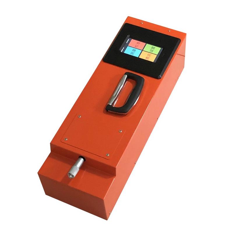

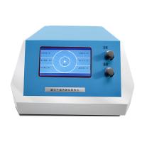
XINGHUO ZTT-201A prominent road sign Measurement Instrument, digital display, multi-angle
ZTT-201A type protruding road sign Measurement Instrument is an instrument for measuring the main performance index of protruding road signs - luminous intensity coefficient. The instrument is suitable for photometry laboratories, testing centers, traffic management departments and branch construction sites, etc.; it is also suitable for protruding road sign manufacturers to product mass inspection.
 TianDiXingHuo
 ZTT-201A
 ZTT-201C

-
JINGWEN JWJ01-1S Pulp manual sheet reader, diameter Φ200mm
$ 1429.00 -
CHINA NBC-1220S Vertical Plug-in Life Tester, Terminal Harness Tester
$ 3505.00 -
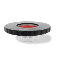
TIANDIXINGHUO XH-BZQ inverse reflection standard
$ 954.00 -
TQC VF2200 Moisture Penetration Cup SH1003 10cm2
$ 508.00 -
Huicheng HCDR-S thermal conductivity Tester, high-low temperature thermal resistance performance test
$ 5124.00


ZTT-201A raised road marking measuring instrument is an instrument for measuring the main performance index of raised road markings - luminous intensity coefficient. The instrument is suitable for photometry laboratories, testing centers, traffic management departments and branch road construction sites, etc.; it is also suitable for the inspection of product quality in raised road sign production plants. The measurement object of this instrument is a rectangular raised road sign.
The main technical basis for the design of the instrument is my country's national standards GB 8416-87, GB/T 3978-1994, GB/T 3979-1997 and GB/T 24725-2009. It also refers to the relevant standards of other countries (such as ASTM-810, ASTM-E 809, DIN 67520). The Detector of the instrument meets the requirements of the CIE (International Commission on Illumination) standard photometric observer, and the color temperature of the light source meets the CIE Standard A light source. Geometric conditions comply with the provisions of CIE Technical Document No. 54. Therefore, the technical conditions of the instrument are consistent with those in the world.
Measurement steps
The measurement steps of the retroreflective luminous intensity coefficient of the raised road signs are as follows:
1. Charging:
The instrument should be fully charged before measurement. The charging method is as follows:
1.1 First turn the instrument switch (8) to the charging position, then connect the charger (11) to the AC power supply (220V, 50Hz), and then insert the charging plug into the electrical socket (9).
1.2 After the power supply is connected, the indicator light on the charger is red, and it is charging at this time until the indicator light turns green, and the battery is fully charged.
2. Zero adjustment:
Adjust zero first when measuring, and the adjustment steps are as follows:
2.1 Do not place the tested sample (or calibration block) on the sample angle plate (14);
2.2 Put the main body of the instrument on the bottom plate (13), and there are alignment groove marks on the lower edges of both sides of the front end of the main body of the instrument, which should be aligned with the positioning blocks on both sides of the bottom plate (13) to align the edges;
2.3 Turn the transfer switch (8) to the measurement position, press the display switch (6), and the display (7) will display numbers;
2.4 Press the measurement switch (12) and the digital display meter (7) displays a number of zero. If it is not zero, turn the zero adjustment knob (4) to make the digital display meter (7) display a number of zero, and the zero adjustment is completed.
3. Instrument calibration:
After the zero position is adjusted, then the instrument is calibrated for the value, the geometric conditions of the calibration block during calibration; the observation angle α=0.2°; the incident angle β1=0°β2=0°. Calibration steps are as follows:
3.1 Remove the host from the bottom plate (13), place the calibration block (15) on the sample angle plate (14) of the bottom plate (13), and the front end of the tested surface should be in line with the raised edge of the sample table (14). Align;
3.2 Rotate the sample angle plate (14) so that the engraved line is aligned with 0 on the incident angle scale (16) on the bottom plate (13) (that is, β2=0°);
3.3 Re-place the host on the bottom plate (13) according to the method in 2.2;
3.4 Adjust the observation angle regulator (1) to 0.2° (that is, α=0.2°);
3.5 Press the measurement switch (12), and observe the reading of the digital display meter (7) after about 1-2 minutes of preheating. After the reading is stable, the value R of the luminous intensity coefficient can be read. This value should be equal to the value given by the calibration block. If they are not equal, adjust the calibration knob (5) to make the displayed value equal to the given value of the calibration block. At this point the instrument has been calibrated and ready for measurement.
4. Indoor sample measurement:
When measuring, first place the sample to be tested on the sample angle plate (14), and adjust the required incident angle β2 and observation angle α. Press the measuring switch (12). The value displayed in the digital display meter (7) after preheating is the luminous intensity coefficient value R of the tested sample. After the measurement is completed, loosen the measurement switch (12), set the display switch (6) to "off", and switch the switch (9) to the off position.
5. Outdoor on-site measurement:
5.1 Before measurement, the zero adjustment and calibration steps of the instrument are the same as the above 2 and 3;
5.2 For on-site measurement, two spare blackboards with square holes are required, one of which has an incident angle (β2) of 0° and the other plate has an incident angle (β2) of 5°;
5.3 Measurement steps:
5.3.1 Insert the hole of the square hole blackboard with an incident angle of 0° into the protruding road sign block to be tested;
5.3.2 Put the host on the blackboard with square holes, the method is the same as that described in 2.2;
5.3.3 Adjust the observation angle (α) to 0.2°;
5.3.4 Turn the transfer switch (8) to the measurement position, and set the display switch (6) to "ON";
5.3.5 Press the measurement switch (12) and observe the display value in the digital display meter (7). After the warm-up is stable, read the displayed value as the luminous intensity coefficient value R;
5.3.6 If α=0.2° and β=5° are determined. The luminous intensity coefficient value, you need to use the incident angle (β2) is 5 ° square hole blackboard, the steps are the same as above;
5.3.7 If it is necessary to measure the luminous intensity coefficient value under other conditions, the steps are the same as above;
5.3.8 After the measurement is completed, the display switch (6) is set to "off", and the transfer switch (8) is turned to the off position.
TianDiXingHuo ZTT-201A Protrusion road sign Measurement InstrumentSpecifications
| LIST | VALUE |
|---|---|
| Observation angle (α) | 0.2 °~ 2.0 ° continuously adjustable |
| Incident angle (including β 1 and β 2) | Beta 1 is +/- 0 ° and Beta 2 is +/- 0 °、 +/- 5 °、 +/- 1 0 °、 +/- 1 5 °、 +/- 2 0 ° |
| Detector | Silicon diode + V (λ) correction (CIE standard photometric observer) |
| Light source Color temperature | 2856K (CIE Standard A Light source) |
| Measurement range | 0~1999 mcd•lx-1 |
| Power | Lithium battery pack 7.4V (Capacity 12Ah) |
TianDiXingHuo ZTT-201A Protrusion road sign Measurement Instrument Packing list
Digital display host X1, each X1 of white and yellow calibrated blocks, indoor angle plate X1, outdoor angle plate X2, charger X1, certificate X1, warranty card X1, manual X1, calibrate certificate (factory) X1, instrument case X1
[Note] Because the manufacturer's packaging may be updated or upgraded, the detailed packaging list shall be subject to the latest standard configuration of the manufacturer.