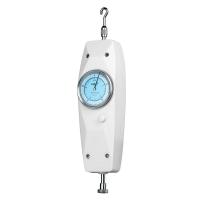


SUNDOO SN-200 Pointer Tensile Pressure Dynamometer, Range 200N
SN-200 Pointer Tensile Pressure Dynamometer is suitable for push-pull load testing in Electronics, Light Industry Textile, Construction Hardware, Lighters and Ignition Devices, Fire Equipment, Pen Making, Lock Making, Fishing Gear, Power Machinery, Scientific Research Institutions and other industries.
 SUNDOO
 SN-200

-
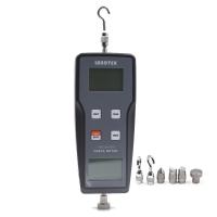
Shandu SHB-100B Digital Force Gauge, Load 100N
$ 359.00 -
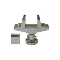
SUNDOO SJ-018 Bending Clamp 100kN
$ 602.00 -
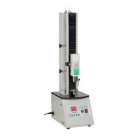
Electric single column vertical machine HDE-500 Hypertherm Force Gauge testing device, can withstand loads up to 500N
$ 662.00 -
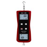
DUBAN DB25-204FM-2N Integrated Force Gauge Electronic Digital Push-pull Meter
$ 252.00 -
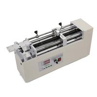
Electric horizontal machine HDT-500 Haibao HF/HG/NK series dynamometer base, load 500N
$ 823.00


Product Description
SN-200 push-pull force gauge is a small and convenient push and pull force testing instrument, which has the advantages of high precision, easy operation and portability, and has a peak value switch operation knob, which can be used for peak load indication and continuous load value indication. It is also equipped with a tolerance zone indicator device to facilitate batch test readings. Please read this manual carefully before using the instrument, so as to make full use of the functions of the instrument and obtain the correct load value during the test. It is suitable for push-pull load testing in industries such as electronic appliances, light industry textiles, construction hardware, lighters and ignition devices, fire-fighting equipment, pens, locks, fishing gear, power machinery, scientific research institutions, etc. It is a new generation product replacing the tubular push-pull force gauge.
main feature
Hand-held design, small size, easy to operate, and can be used in combination with various fixtures;
Pointer indication, convenient reading, high test accuracy;
Free switch between peak protection function and continuous load indication;
The tolerance zone indicator device can realize the upper and lower limit setting;
Two units of Newton and kilogram (units can be customized) are displayed at the same time, without unit conversion;
One year warranty, long-term maintenance;
Patent design, patent number: ZL200520074355.1.
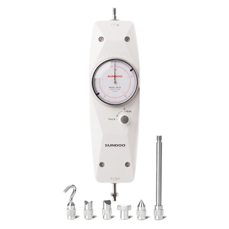
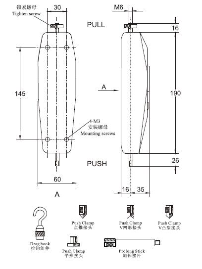
Structure and Dimensions

test operation
Please hold the push-pull gauge firmly with both hands or install the push-pull gauge on a suitable machine for testing. When testing, please put the object under test and the push-pull gauge in a straight line before performing the test. If the object under test and the push-pull gauge are not in a straight line, the correct load value will not be obtained during the test.
Preparation before the test
Select a suitable test connector fixture and install it on the push-pull force gauge.
1. Tensile test
Install the attached pull jig on the center shaft at the [PULL] end marked.
2. Compression test
Select an appropriate test jig from the attached push jig, and install it on the center shaft at the end marked with [PUSH].
3. Utilization of extended post
When the object under test cannot be reached, use the attached quickening post to install the fixture.
Note: When using the extension rod to test, the object under test and the push-pull force gauge must be on the same straight line. If they are not on a straight line, the correct load value of 1g will not be obtained.
4. Confirmation and operation method of the switching knob
①Switching between peak load [PEAK] and continuous load [TRACK] Press the switching knob slightly down and turn it to the left at the same time, so that the " · " mark of the knob is on the position of continuous load [TRACK].
②To switch between continuous load [TRACK] and peak load [PEAK], turn the switch knob to the right, and the knob will pop up, and the " · " mark of the knob is on the position of peak load [PEAK].
③Precautions after the test—after the test is completed, switch the “·” mark of the knob, and place it at the peak load [PEAK] position. If the switching knob is placed in the continuous load [TRACK] position for a long time, the service life of the internal zero-setting spring will be shortened.
5. Dial adjustment
①Check that the pointer is aligned with [0] on the dial. If it is not aligned, please rotate the scale to adjust the garden, and the scale will act together to make the pointer align with the [0] position.
②When the instrument is placed vertically, especially when a fixture is installed, the pointer will deviate from [0] even if no load is applied, which is due to the weight of the instrument and the fixture. At this time, the scale should be adjusted by rotating it so that the [0] of the dial aligns with the pointer, and then proceed to the test.
6. Tolerance indicator band setting
Turn the two needles on the tolerance indicator to set the desired upper and lower tolerance limits for the test. During the test, when the pointer of the push-pull gauge is within the indication range of the tolerance indicator, it means that the test value is the set qualified value; when the pointer of the push-pull gauge is outside the range of the tolerance indicator, it means that the test value is the set value Determine the unqualified value.
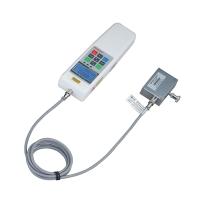
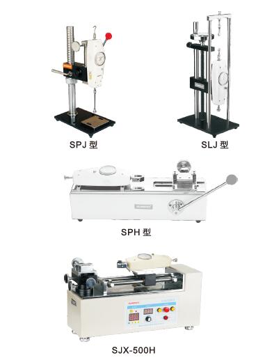
Optional test stand (sold separately)
SUNDOO SN-200 Tension and Compression Force Gauge (Pointer Type)Specifications
| LIST | VALUE |
|---|---|
| Maximum measurement | 200N |
| Load Graduation | 1.0N |
| Error of indication | ±1%FS |
| Dimensions | 232*60*51mm |
| Weight | About 0.6KG |
SUNDOO SN-200 Tension and Compression Force Gauge (Pointer Type) Packing list
host x1, manual x1, warranty card x1, certificate of conformity x1.
[Note] Because the manufacturer's packaging may be updated or upgraded, the detailed packaging list shall be subject to the latest standard configuration of the manufacturer.