Reader's Guide
This manual is compiled based on manufacturer's data. Due to equipment batch changes, the content may not fully match every physical unit. Please refer to the actual operation and on-device labels.
Copyright belongs to the manufacturer. For internal reference of purchasers only. If safety parameters in the manual differ from the physical unit, please suspend operation and consult our engineer for confirmation.
Disclaimer: This manual is for reference only. In case of any discrepancy, the physical unit shall prevail. Our company assumes no liability for any consequences arising from operations based on this manual.
HUXI 2XZ-B series, Vacuumpump manual
2XZ-B series
Table of Contents
| 1. Overview | (1) |
| 2. Technical Performance Parameters | (1) |
| 3. Brief Description of Working Principle and Structure | (2) |
| 4. Installation instructions | (3) |
| 5. Usage Methods and Precautions | (3) |
| 6. Maintenance and servicing | (4) |
| 7. Performance Curve | (5) |
| 8. Faults and Troubleshooting Methods | (6) |
| 9. Packing list | (7) |
| 10. External dimensions | (8) |
Note: Please read this manual carefully before turning on the device.
1. Overview
The 2XZ-B rotary vane vacuum pump is a two-stage high-speed direct-coupled rotary vane vacuum pump. This pump is the basic equipment used to extract gas from sealed containers to obtain vacuum. It can be used independently or as a pre-extraction pump for various high-vacuum systems (booster pumps, diffusion pumps, molecular pumps), and as a pre-extraction pump for maintenance and titanium pumps. It can be used in the manufacturing of electrical vacuum devices, such as vacuum tubes and TV picture tubes, as well as in the freeze-drying industry, especially lithium bromide air conditioners and refrigerators.
This pump features light weight, compact size, low noise, no oil return when stopped, and easy start-up. The pump is equipped with a gas ballast valve that can extract a small amount of condensable water vapor. The gas ballast valve extends the service life of the pump oil and prevents water mixing with the pump, thereby improving the pump's performance.
The exhaust outlet of this pump (except for 2XZ-2B and 4B) can be equipped with an oil mist collector (oil cover). Our company has installed a dual anti-oil backflow device at the air inlet, so the pump is stopped and oil never flows back. This way, users can avoid installing solenoid inflation valves.
This pump operates continuously at the inlet air pressure below 1330Pa, with long service life, stable vacuum, and no oil backflow.
2. Technical Performance Parameters
| Parameters\Model | 2XZ-2B | 2XZ-4B | 2XZ-6B | 2XZ-8B | 2XZ-15B | 2XZ-25B |
|---|---|---|---|---|---|---|
| Pumping rate (L/s) | 2 | 4 | 6 | 8 | 15 | 25 |
| Ultimate pressure (Pa) is the partial pressure | ≤4×10⁻² | ≤4×10⁻² | ≤4×10⁻² | ≤4×10⁻² | ≤4×10⁻² | ≤4×10⁻² |
| Ultimate pressure (Pa) Total pressure | ≤1 | ≤1 | ≤1 | ≤1 | ≤1 | ≤1 |
| Speed (r/min) | 1400 | 1400 | 1400 | 1400 | 1400 | 1400 |
| Motor Power (kW) | 0.37 | 0.55 | 0.75 | 1.1 | 1.5 | 2.2 |
| Power supply voltage (V) | 220/380 | 220/380 | 220/380 | 380 | 380 | 380 |
| Air intake diameter (mm) | φ30 (KF-25) | φ30 (KF-25) | KF-25 | KF-40 | KF-40 | KF-50 |
| Air outlet diameter (mm) | F22 | F22 | KF-25 | KF-25 | KF-25 | KF-40 |
| Noise (dBA) | 65 | 66 | 68 | 70 | 70 | 72 |
| Oil Capacity (L) | 1 | 1.2 | 2 | 3 | 4 | 5 |
| Dimensions (mm) | 514×168×282 | 565×168×282 | 565×200×342 | 650×240×430 | 700×240×430 | 770×240×430 |
| Gross Weight/Net Weight (Kg) | 22/20 | 24/22 | 44/40 | 65/60 | 78/72 | 143/135 |
3. Brief Description of Working Principle and Structure
The 2XZ-B vacuum pump is a positive displacement pump that operates continuously inside the pump chamber using rotary vanes. The pump chamber is divided into two chambers of different volumes, which periodically expand and contract, drawing in, compressing, and discharging gas to achieve a vessel vacuum.
This pump consists of two chambers connected in series front and rear rotating at equal speed in the same direction. The air being drawn is drawn in from the preceding pump (advanced pump chamber), compressed and discharged, then a small amount of gas is discharged into the lower pump chamber (lower chamber), which is compressed and discharged from the pump chamber, and is discharged outside the pump through the exhaust port to achieve a vacuum. See Figure (1).
Figure (1)
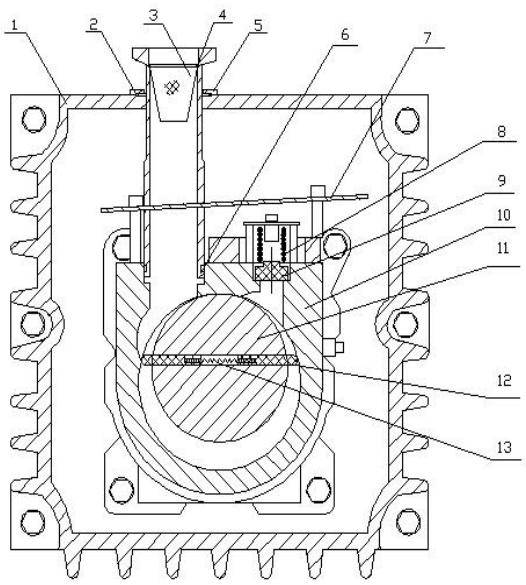
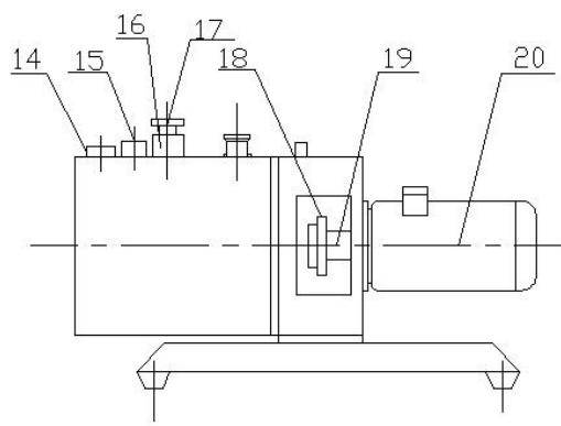
1. Oil tank 2. Intake pipe sealing ring 3. Filter screen 4. Intake pipe 5. Intake pipe pressure plate 6. Intake nozzle "O" ring 7. Fuel baffle 8. Exhaust valve spring 9. Exhaust valve plate 10. Stator 11. Rotor 12. Rotating vane 13. Rotary vane spring 14. Fuel plug 15. Air ballast valve 16. Fog reducer 17. Exhaust port 18. Coupling 19. Cover plate 20. Motor
Figure (2)
Forced oil pump inlet (Type B pump)

1. Low-level pump cover for oil pump 2. Low-stage rotor component 3. Oil pump rotary vane spring 4. Oil pump rotary vane 5. Oil inlet nozzle 6. Oil pump valve plate 7. Oil pump spring 8. Pressing screw 9. Nut 10. Oil pump cover
This pump is equipped with a forced oil pump inlet device, which compulsively forces automatic oil intake, overcoming the drawbacks of other pumps that cannot operate under atmospheric conditions, ensuring sufficient lubricating oil in the pump chamber, and greatly extending the pump's lifespan. All seals of this pump use fluororubber to ensure no oil leakage and environmental pollution.
4. Installation instructions
Open the box and check whether the pump is damaged during transportation and whether it meets factory requirements.
Pumps should be installed in dry, ventilated, and clean areas.
The pump base has rubber foot; besides transportation and moving devices, it can be placed steadily and can be used independently or installed in the frame. Four screws of Φ8mm × Φ14mm are available (screw length selected according to actual conditions).
A 220V motor comes with a power cord when it comes from the factory. For 380V voltage, the factory does not come with a power cord. A professional electrician must install and connect the wiring, and pay attention to the pump's rotation direction when needed.
The pump's inlet and exhaust ports use KF series international standard quick-release flange connections. The 2XZ-2B and 4B are standard straight insertion pipes, with diameters tailored to user requirements.
The connecting pipeline to the pump's air inlet should not be too long. Be sure to check that the external connection pipes, joints, and containers of the vacuum pump are not leaking air and must be sealed, otherwise it will affect the ultimate vacuum and the service life of the vacuum pump.
5. Usage Methods and Precautions
First, unscrew the oil filling plug. For smaller models below 2XZ-4B, fill the oil from the filler hole to half of the oil gauge, while for other pumps, fill up to two-thirds of the oil gauge. Due to factory transportation, no pump oil is injected inside the vacuum pump body (except for 2XZ-6B). If the oil level is too low, it cannot seal the exhaust valve, affecting vacuum level; excessively high may cause oil spray. The pump oil uses the standard number SH0528 for mineral oil type vacuum pump oil in the petrochemical industry, paired with HFV-M100, HFV-M200, HFV-A100, SV-68, CV-A100, CV-AH100, and others.
Pump working environment: temperature ranges from 5°C to 40°C. When the ambient temperature is high, oil temperature rises, viscosity decreases, and saturated vapor pressure increases, causing a slight decrease in vacuum level. Ventilation and heat dissipation should be strengthened to improve the pump's working environment.
Check the pump's ultimate vacuum using a compression mercury vacuum gauge (Maxill meter) as the standard. For example, after thorough pre-sampling and calibration, the pump inlet is directly connected to the vacuum gauge. After 10 minutes of operation, the vacuum pump temperature stabilizes and the vacuum meets the maximum vacuum.
If the relative humidity is high or the extracted gas contains a large amount of condensable steam, connect the pumped container and open the gas ballast valve cap to purify it.
The following situations cannot be used:
Do not inhale gases containing particulates, dust, or gel-like, water-like, liquid, or corrosive substances.
Do not inhale gases containing explosive gases or those with excessively high oxygen content. In this environment, an explosion-proof vacuum pump should be more appropriate.
There should be no pipeline system leaks or containers that match the vacuum pump's suction rate that are too large, operating under prolonged suction.
The pump can continue running at an intake pressure ≤ 1.33×10³ Pa.
The pump is equipped with dual anti-oil backflow devices to prevent oil backflow.
6. Maintenance and servicing
Keep the pump chamber clean, and strictly prohibit impurities from being injected into the pump chamber.
Maintain the oil level. The oil level should be at the center line, not too high, not too low.
If improper storage allows moisture or other volatile substances to enter the pump chamber, the gas ballast valve can be opened to purify them. If the limit vacuum is affected, consider changing the oil. When changing the pump oil, run for about 5 minutes to drain the dirty oil. While draining, slowly add a small amount of clean vacuum pump oil through the air inlet to flush the inside of the pump chamber.
Do not mix with diesel, gasoline, or other oils with high saturated vapor pressure to avoid reducing the ultimate vacuum. When removing and cleaning internal pump parts, generally wipe with gauze. If there are metal fragments, sand, mud, or other harmful substances that need cleaning, gasoline or similar substances can be used to scrub and dry before assembly.
If the pump noise increases or it suddenly jams, immediately cut off the power and conduct inspection.
Disassembly sequence for this series of pumps:
Drain the oil.
Loosen the intake pipe pressure plate screw and pull out the intake pipe.
Loosen the gas suppressor plate screw and pull out the gas ballast.
Remove the fuel tank.
Remove the protective cover, remove the hex socket screw connecting the support to the pump, loosen the pump coupling fastening screws, extract the pump body assembly, and remove the pump body components. Whether to remove the motor depends on its quality.
Remove the oil baffle, the upper and lower exhaust valve covers, and whether to remove the air duct pressure cover depends on the situation.
Remove the oil pump cover, take out the oil pump rotary blade, loosen the screws at both end pump covers, carefully remove both end pump covers, and extract the high- and low-stage rotors and rotary blades.
If the rotor or stator is worn, it should be inspected, repaired, or replaced.
Clean all components and clear all oil inlet holes for installation.
Assembly sequence:
First, install the advanced rotating blade (long) with the rotating vane spring, insert it into the advanced rotor slot, then install it into the advanced pump chamber, install the advanced pump cover, tighten the screws evenly, and use the pump coupling to manually rotate a few times. There should be no lag or a noticeable sense of lightness or weight.
Refer to 7.1 for installing the advanced rotor and install the low-level rotor. Then install the oil pump rotary vane, spring, and oil pump cover, and manually rotate the pump coupling a few times; there should be no lag or a noticeable sense of weight.
Install the oil inlet device and other components.
Reinstall the exhaust valve plate, oil tank, oil baffle, and other parts.
Reinstall the pump body, keys, and coupling back onto the support.
Install the oil tank, return air suppression valve, intake pipe, and tighten the flange.
Install protective covers on both sides of the bracket.
Screw on the drain plug, then add oil from the oil fill hole to the required oil level.
Before the pump starts, check whether the pump is running forward and backward by instantly jogging the power supply. Only after this is complete can it be used.
7. Performance Curve Chart

8. Faults and Troubleshooting Methods
| Fault phenomena | Causes of occurrence | Elimination methods |
|---|---|---|
| Poor vacuum quality | 1. Insufficient oil supply, resulting in contamination | Add new oil or replace it |
| 2. The air inlet and air ballast valve sealing ring are damaged, or the external pipeline connection is leaking | Replace the Type 0 sealing ring and eliminate the leak area | |
| 3. The exhaust valve plate is damaged or trips out of the cavity | Replace the exhaust valve plate and return it to its original position | |
| 4. Oil circuit blockage | If the oil is dirty, change it; if the check valve spring malfunctions, replace it. If the pump filter screen or oil inlet is blocked, clear the issue | |
| 5. Inhaled gas temperature too high, pump oil temperature rises too high (atomization) | Improve ventilation, lower pump temperature, and lower the temperature of the pumped gas | |
| 6. Rotor and stator wear, rotor spring breakage | Carry out major overhauls and swap parts | |
| Operational failure | 1. Oil circuit blockage, no pump oil lubricating dry grinding inside the pump chamber | Check the oil inlet system; if the oil is dirty, replace with new oil |
| 2. Foreign objects, impurities, chemicals, and solutions are inhaled inside the pump chamber | Disassemble the pump for cleaning, then add a vacuum pump filter | |
| 3. Wiring errors, phase loss, or incorrect ground wires | Inspection and correction | |
| Oil leak | 1. Poor sealing of the fuel tank gasket and drain plug | Tighten the sealing screws or replace the gasket |
| 2. Oil gauge leaks | Replace the oil gauge, tighten screws, or replace the gasket | |
| 3. Wear of the pump shaft frame oil seal | Replace the oil seal | |
| Abnormal noise | 1. The fan blade inside the motor touches the cover | Adjust the position of the fan and cover |
| 2. Oil circuit blockage, no pump oil lubricating dry grinding inside the pump chamber | Check if the oil inlet hole is blocked or if the oil is too dirty; replace the oil | |
| 3. Pump and motor couplings are loose | Adjust the locking screw of the tightening coupling | |
| 4. Motor failure | Replace the motor or perform maintenance and repairs | |
| 5. The rotating vane spring breaks | Disassemble the pump chamber and swap the rotary vane spring | |
| 6. Foreign objects inside the pump chamber, abnormal rotation | Disassemble the pump for cleaning and remove impurities | |
| 7. Loose fastening screws on all components | Inspect all components and tighten the screws | |
| Oil return | 1. The check valve of the oil pump supply system is damaged | The air inlet is equipped with an electromagnetic vacuum inflation valve and an electromagnetic vacuum pressure differential valve |
| Spray oil | 1. Excessive oil stored in the pump, resulting in a high oil level | Release excess oil |
| 2. Open and spacious usage | It is strictly forbidden to use the device in open air or install oil mist collectors | |
| Fever and smoke | 1. Smoke coming from the exhaust outlet, pump body and motor overheating | Check the pump inlet and external pipelines, as well as the joints and external containers for leaks, and ensure they are sealed. Check if the oil circuit is blocked |
| 2. Oil circuit blockage, no pump oil lubricating dry grinding inside the pump chamber |
9. Packing list
| Category | Name | Specifications | 2XZ-2B | 2XZ-4B | 2XZ-6B | 2XZ-8B | 2XZ-15B | 2XZ-25B |
|---|---|---|---|---|---|---|---|---|
| Main unit | Vacuum pump | 1 | 1 | 1 | 1 | 1 | 1 | |
| Other accessories | Quick-release flange KF-25 | 2 | 1 | 1 | ||||
| Quick-release flange KF-40 | 1 | 1 | 1 | |||||
| Quick-release flange KF-50 | 1 | |||||||
| Machine foot screws | 4 | 4 | 4 | 4 | ||||
| Vacuum pump oil HFV-A100 | 1 | 1 | 1 | |||||
| Vacuum pump oil HFV100 | 1 | |||||||
| Vacuum pump oil HFV-68A | 1 | 1 | 1 | |||||
| Documents | User manual | 1 | 1 | 1 | 1 | 1 | 1 | |
| Certificate of Conformity | 1 | 1 | 1 | 1 | 1 | 1 | ||
| Quality guarantees three guarantees | 1 | 1 | 1 | 1 | 1 | 1 |
10. Dimensions drawing
Figure (4) Appearance and Installation Dimensions
| Model | L | L1 | L2 | L3 | l | l1 | l2 | W | W1 | W2 | w1 | w2 | H1 | H2 | DN | KF | Φd |
|---|---|---|---|---|---|---|---|---|---|---|---|---|---|---|---|---|---|
| 2XZ-2B | 488 | 171 | 47 | 39 | 300 | 270 | 109 | 130 | 43 | 44 | 94 | 134 | 250 | 230 | 25 | 25 | 6 |
| 2XZ-4B | 528 | 211 | 47 | 39 | 300 | 270 | 109 | 130 | 43 | 44 | 94 | 134 | 250 | 230 | 25 | 25 | 6 |
| 2XZ-6B | 550 | 220 | 105 | 64 | 302 | 250 | 85 | 175 | 55 | 66 | 136 | 182 | 315 | 280 | 25 | 25 | 7 |
| 2XZ-8B | 624 | 255 | 175 | 64 | 495 | 455 | 180 | 238 | 75 | 100 | 182 | 232 | 414 | 388 | 25 | 40 | 8 |
| 2XZ-15B | 703 | 315 | 175 | 64 | 495 | 455 | 180 | 238 | 75 | 100 | 182 | 232 | 414 | 388 | 25 | 40 | 8 |
| 2XZ-25B | 743 | 355 | 175 | 64 | 495 | 455 | 180 | 238 | 75 | 100 | 182 | 232 | 414 | 388 | 25 | 50 | 8 |


- 1HUXI 2XZ-B Series, Rotary Vane Vacuumpump Instruction Manual
- 2HUXI ultrasonic cell crusher instruction manual
- 3HUXI HB-20 Corrosion Resistant Diaphragm Pump Instruction Manual
- 4HUXI HB-40B Corrosion resistant diaphragm pump instruction manual
- 5HUXI MD200 series, dry Nitrogen blowing instrument instruction manual
- 6HUXI HY-1200 In situ hybridization instrument instruction manual
- 7HUXI HW-200G/TG microplate incubator instruction manual
- 8HUXI JB series digital display constant speed powerbasic stirrer instruction manual
- 9HUXI Vortex Series, Instruction Manual for Vortex Mixer
- 10HUXI HT-200 Series Multi-Tube Vortex Mixer Instruction Manual