Reader's Guide
This manual is compiled based on manufacturer's data. Due to equipment batch changes, the content may not fully match every physical unit. Please refer to the actual operation and on-device labels.
Copyright belongs to the manufacturer. For internal reference of purchasers only. If safety parameters in the manual differ from the physical unit, please suspend operation and consult our engineer for confirmation.
Disclaimer: This manual is for reference only. In case of any discrepancy, the physical unit shall prevail. Our company assumes no liability for any consequences arising from operations based on this manual.
SANFA SHP-100/160/250/300/400/500 biochemistry cultivating box instruction manual
1. Scope of Application
This product is a high-precision constant temperature device with temperature and cold control. It is a constant temperature cultivation device for bacteria, mold, and microbial culture and breeding experiments. It is especially suitable for scientific research and production in fields such as biological genetic engineering, medical research, health and epidemic prevention, drug inspection, environmental protection, rural science, aquaculture, and animal husbandry.
2. Technical Indicators
| Model | SHP-100 | SHP-160 | SHP-250 | SHP-300 | SHP-400 | SHP-500 |
| Volume | 100L | 160L | 250L | 300L | 400L | 500L |
| Refrigerants | Fluorine-free | |||||
| Ambient temperature | 10~30°C | |||||
| Temperature range | 0~60°C | |||||
| Temperature uniformity | ±1.5°C | |||||
| Temperature fluctuations | ±1°C | |||||
| Power supply | 220V 50HZ | |||||
| Maximum power consumption | 300 W | 500 W | 650 W | 800 W | 1000W | 1500W |
3. Overview of the structure
The outer shell of this product is made of high-quality steel plates with a powdered surface. The chamber uses stainless steel plate, which is durable and corrosion-resistant. The outer door is equipped with an observation window and double-layer insulated glass doors for easy observation of temperature tests inside the chamber.
Panel indicators

SHHB-C6006 indicator light definition:
[MAIN] Indicator Light: This light turns on during normal operation (not set state) and turns off otherwise.
[SET] Indicator Light: When set to the right state, this light turns on; if not, it turns off.
【RUN】 Indicator Light: When the timer ends, this light turns off; instead, it stays on.
【STOP】 Indicator Light: When the timer ends, this light turns on; otherwise, it turns off.
[ALM] Indicator Light: When there is a temperature deviation alarm or abnormal temperature measurement, this light turns on; when there is a temperature deviation alarm, the light flashes; under normal operating conditions, the light turns off.
[HEAT] Indicator Light: When there is heating output, this light turns on; if not, it turns off.
[COOL] Indicator Light: When there is cooling output, this light turns on; during the startup delay, it flashes; if it goes off, it does not.
[OUT1] Indicator Light: When there is lighting output, this lamp turns on; if it is turned off, it turns off.
[OUT2] Indicator Light: When the defrosting solenoid valve outputs, this light turns on; if not, it turns off.
4. Operating Methods
1. Power on the controller; the upper row of the display window displays the [division number and instrument model], while the lower row shows the [version number].
After 3 seconds, it returns to normal display mode
2. Reference and setting of temperature and time
Note: Timing function and timing mode (positive/countdown) are selectable. For details, see the values of ndt and ndE parameters in the internal parameter table-2.
1) If there is no timer function:
Click the [Set] key to enter temperature setting mode. The upper row of the display window displays the prompt "SP", and the bottom row shows the temperature setting value. You can modify it to the desired value using the [Increase], [Decrease], and [Shift] keys. Then click the [Settings] key to exit this setting, and the modified settings will be saved automatically.
2) If there is a timer function,
Click the [Set] key to enter the temperature setting mode. The upper row of the display window displays the prompt "SP", the lower row shows the temperature setting value. The modification method is the same as above; Then click the [Set] button to enter the time setting mode. The upper row of the display window displays the prompt "ST", and the bottom row shows the time set value; Then click the [Settings] key to exit this setting state, and the modified settings will be saved automatically.
When the time is set to "0", it means there is no timer function, the instrument runs continuously, and the lower display window displays the temperature set value; When the set time is not "0", the lower row of the display window shows the running time, the "time unit" lights up, and when timing starts, the "time unit" flashes. When the timing time is up, running ends, the bottom display window shows "End", and the buzzer sounds intermittently for EST seconds (see internal parameter table-2) before stopping. After the scheduled run ends, press and hold the [Decrease] button for 3 seconds to restart the program.
3. Abnormal temperature measurement alarm
If the upper row of the display window shows "----", it means the temperature sensor is faulty, the temperature exceeds the measurement range, or the controller itself is faulty. The controller automatically cuts off the heating output, the buzzer sounds continuously, and the alarm light stays on. Please carefully check the temperature sensor and its wiring.
4. When the upper deviation overtemperature alarm occurs, the buzzer beeps and beeps, the "ALM" alarm light stays on, and the heating output is cut off; When the lower deviation overtemperature alarm occurs, the buzzer beeps and beeps, and the "ALM" alarm light flashes; If an over-temperature alarm occurs due to changing the temperature setting, the "ALM" alarm light will not light up, and the buzzer will not sound.
5. In normal display mode, press and hold the add button for 2 seconds to manually lock the screen; while locked, press the add button to unlock the screen; Alternatively, on the main interface, after a certain period without pressing a button, the screen will automatically lock (see internal parameter table-1 Parameter LCT for details).
6. When the buzzer sounds, any key can be pressed to silence it.
5. Reference and Setting of Internal Parameters
In normal display mode, press and hold the [Set] button for 3 seconds. The top row of the display window will display the password prompt "Lc", and the bottom row will show the password value. Use [Increase], [Decrease], and [Shift] to change the desired password value. Then click the [Set] key. If the password value is incorrect, the controller will automatically return to normal display. If the password value is correct, it enters the internal parameter setting state. Clicking the [Set] key again allows you to modify each parameter in sequence. Press and hold the [Set] button for 3 seconds to exit this state, and the parameter values will be saved automatically. See the table below:
Internal parameter table -1
| Parameter refers to | Parameter name | Parameter and function descriptions | (Scope) Factory-made |
| Lc | Password | When "Lc=3", parameter values can be viewed and modified. | 0 |
| ALH | Upper deviation overtemperature alarm | When "temperature measurement value > temperature setpoint + ALH", an upper deviation overtemperature alarm occurs (see 5.4). | (0~50.0°C)5.0 |
| ALL | Lower deviation overtemperature alarm | When "temperature measurement value < temperature setpoint + ALL", there is a lower deviation overtemperature alarm (see 5.4). Note: When "ALL = 0", the lower deviation alarm is invalid. | (-50.0~0°C)0 |
| Lct | Lock screen time | Automatic lock time: no automatic lock at 0 hours, no lock function at -1 hour. | (-1~999 seconds) 0 |
| Ct | Compressor startup delay | Compressor startup delay protection time: The minimum time interval from compressor stop to restart. | (0~600 seconds) 180 |
| FIL | Filter coefficient | Temperature measurement filter coefficient. | (1~200)50 |
| Lt | Lighting is turned off with a delay | When the light is on, it automatically turns off after a delayed Lt period. | (0~30 points) 2 |
| Cnd | Compressor start-stop mode | Effective only when the compressor operates intermittently! 0: Automatic start-stop compressor (determined automatically by controller) 1: Manual start-stop compressor (using uP and dn values) | (0~1)0 |
| uP | Compressor start threshold | It only works when the compressor operates intermittently and is "Cnd=1"! If "temperature measurement value ≥ temperature setpoint + uP" and the compressor startup delay time is up, start the compressor. If "temperature measurement value < temperature setpoint + dn", | (-10.0~10.0°C) |
| dn | Compressor shutdown threshold | (-10.0°C~uP)0.4 | |
| P | Scale band | Time proportional effect adjustment. | (0.1~80.0°C)10.0 |
| I | Scoring time | Integration regulation. | (1~2000 seconds) |
| d | Differential time | Differential action regulation. | (0~1000 seconds) |
| T | Control cycle | Heating control cycle. | (1~60 seconds) 5 |
| Pb | Correction of measurement temperature deviation | It is usually used to correct errors generated during low-temperature measurements. Pb = actual temperature value - instrument reading | (-50.0~50.0°C)0 |
| PL | Measurement temperature slope correction | It is usually used to correct errors generated during high-temperature measurements. PL = 1000 × (actual temperature value - instrument reading) ÷ instrument reading | (-999~999)0 |
| Adr | Mailing address | Local communication address. | (1~32)1 |
Internal parameter table -2
| Parameter refers to | Parameter name | Parameter and function descriptions | (Scope) Factory-made |
| Lc | Password | When "Lc=9", parameter values can be viewed and modified. | 0 |
| ndA | Temperature alarm method | 0: Only temperature deviation over-temperature alarm 1: Simultaneous temperature deviation above and below temperature over-temperature alarm | (0~1)0 |
| FCH | Types of fans | 0: Long-shaft fan; 1: Short-shaft fan Note 1 | (0~1)0 |
| ndc | Compressor operating mode | 0: The compressor operates only intermittently; 1: The compressor determines whether it operates in balanced mode or intermittent mode based on the CP value (see below); 2: The compressor is determined based on the value of Htd (see below). | (0~2)0 |
| CP | Compressor operating mode is fixed switching point | When "ndc=1", if the "temperature set value is ≥CP", the compressor operates intermittently; conversely, it operates in a balanced mode. | (0~200.0°C)30.0 |
| Htd | Automatic switching point for compressor operation | When "ndc=2", if "temperature set value ≥ambient temperature + Htd", the compressor operates intermittently; conversely, it operates in a balanced mode. | (-50.0~50.0°C)0.0 |
| AnP | Do not operate at compressor operating temperatures | When the "temperature measurement value ≥ AnP", compressor operation is strictly prohibited. | (0~200.0°C)60.0 |
| CnP | Do not turn on the compressor operating temperature | When the "temperature setpoint" ≥CnP", the compressor is only turned on once if the temperature reading exceeds the set value. | (0~200.0°C)42.0 |
| ndt | Timer function | 0: No timer function; 1: Constant temperature and timer; 2: Startup timer; | (0~2)1 |
| ndE | Scheduled methods | 0: Positive timing, meaning the main interface's time bar displays the accumulated time; | (0~1)0 |
| Hn | Units of time | 0: Minute timing; 1: Hourly timing | (0~1)0 |
| SPd | Temperature deviation | If the temperature measurement differs from the set value within SPd, the temperature enters the constant temperature stage. | (0.1~50.0°C)0.5 |
| EST | Timer ends with a time reminder | When the timer ends, the buzzer will indicate the time. Note: When "EST=9999" is used, it indicates a permanent prompt. | (0~9999 seconds) 60 |
| EH | Whether the timed end will continue | 0: Turn off all output after the timer ends; 1: After the timer ends, continue temperature control. | (0~1)0 |
| nP | Maximum power output | Maximum power percentage output by heating. | (0~100%)100 |
| Lco | During low temperature control | When "temperature measurement value ≥ temperature setpoint + Lco", the heating output is turned off. Note 2 | (-10.0~10.0°C)-0.5 |
| SPL | Minimum temperature set value | The minimum temperature set value. | (-90.0~50.0°C) |
| SPH | Maximum temperature setting | Maximum temperature set value. | (SPL~200.0°C)80.0 |
Note 1: If the fan used in the equipment generates heat and causes a significant temperature rise in the controlled object, please select a short-shaft fan.
Note 2: Effective only when the compressor operates intermittently and the "temperature set value < ambient temperature".
Internal parameter table -3
| Parameters | Parameter name | Parameter and function descriptions | (Scope) Factory-made |
| Lc | Password | When "Lc=18", you can view the ambient temperature. | 0 |
| Ht | Ambient temperature | Displays the current ambient temperature of the controller. | |
| HPb | Correction of ambient temperature deviation | HPb = Actual ambient temperature - displayed ambient temperature Ht value. | (-50.0~50.0°C) 0 |
Internal parameter table -4
| Parameter refers to | Parameter name | Parameter and function descriptions | (Scope) Factory-made |
| Lc | Password | When "Lc=567", you can view and modify parameter values. | 0 |
| rST | Restore factory values | 0: Cancel factory reset values; 1: Confirm the factory value has been restored. | (0~1) 0 |
Internal parameter table -5
| Parameter instructions | Parameter name | Parameter and function descriptions | (Range) Ex-factory value |
| Lc | Password | When "Lc=27", you can view and modify parameter values. | 0 |
| ndH | Alarm relay power | 0: Alarm relay for alarm output function; 1: The alarm relay serves as a timed end reminder. | (0~1)0 |
| ndu | Relay operating mode | 0: Operates according to the set value: When the "temperature setpoint $\geqslant$ dP" is reached, the relay's normally open point closes. When the "temperature set value < dP" and the "temperature measurement value <dP + 3.0°C" relay normally open point, it is open. 1: Operates according to the measured value: When the "temperature measurement value $\geqslant$ dP", the relay's normally open point is closed. In "Temperature Measurements." < | (0~2)0 |
| dP | Boundary point | Temperature indexing points, set according to NDU parameters. | (-90.0~200.0°C) 15.0 |
| duL | Pressure relief solenoid valve starter valve | When the compressor is operating in balanced mode, if "temperature measurement $\leqslant$ temperature setpoint + duL", activate the pressure relief solenoid valve; When the compressor is operating in a disconnected mode, if the compressor stops | (-5.0~0.0°C)0.0 |
| duH | Pressure relief solenoid valve closing threshold | When the compressor is operating in balanced mode, if "temperature measurement $\geqslant$ temperature setpoint + duH", close the pressure relief solenoid valve; When the compressor operates in a disconnect mode, if the compressor starts running, close the pressure relief solenoid valve. Note: When the compressor operates in balanced mode, if "duL=0" and "duH=0", the pressure relief solenoid valve will always be used | (0.0~5.0°C)0.0 |
| ndF | Evaporator defrosting method | 0: No defrosting function; 1: Solenoid valve frosting; 2: Heating tube defrosting; | (0~2)0 |
| dT1 | Defrosting interval 1 | The defrosting time interval when the "temperature setpoint $\leqslant$ 8.0°C". Note: 0 indicates no frosted in this segment. | (0~240 hours) 12 |
| FT1 | Defrosting time 1 | Defrosting start time when the "temperature setpoint $\leqslant$ 8.0°C" is activated | (0~600 seconds) 30 |
| dT2 | Frost interval: 2 | The defrosting time interval when the temperature setpoint is "8.0°C< $\leqslant$ 15.0°C". Note: 0 indicates no frosted in this segment. | (0~240 hours) 24 |
| FT2 | Defrosting time 2 | The defrosting start time when the temperature setting is "8.0°C< $\leqslant$ 15.0°C. | (0~600 seconds) 30 |
| dT3 | Defrosting interval: 3 | The thawing time interval when the temperature setpoint is "15.0°C< $\leqslant$ 20.0°C". | (0~240 hours) 48 |
| FT3 | Defrosting time 3 | The defrosting start time when the temperature setting is "15.0°C< $\leqslant$ 20.0°C". | (0~600 seconds) 30 |
6. Notes
During transport, do not invert the product or lay it flat at a distance greater than 45 degrees.
Do not frequently set the temperature during use to avoid overload and lifespan from frequent compressor starts.
When lighting is not needed inside the box, turn off the lighting with just one press to avoid affecting the upper temperature and extend the lamp's operating time.
Do not store too many cultivated items inside the box; leave gaps when arranged to facilitate air circulation inside the box.
Never touch or collide with the temperature sensor inside the box to avoid damage and loss of control.
Do not use acidic, alkali, or other corrosive solutions to wipe the surface; wipe clean with a dry cloth. When the equipment is not in use, keep the inside of the box dry and turn off the power switch to set to the "0" position.
This product must be operated and maintained by professionals; non-electrical personnel are not allowed to repair the equipment, and live-line maintenance is strictly prohibited.
Please carefully read the product manual before using this equipment before performing any operations.
7. Electrical Principle Wiring Diagram

8. Fault Handling
| Phenomenon | The reason | Processing |
| The temperature zone on the display shows "0000". | Sensor open or short circuit | Check the sensor |
| The unit is not operating | Power outage Fuse blows Poor power contact | Wait until power is available before use Replace the fuse Reinstall |
| No cooling | Refrigerant leaks Capillary tube blockage The axial fan does not rotate | Request professional inspection Request professional inspection Testing or replacement |
| Poor temperature performance | Cultivating items is too dense Ambient temperature is too high or too low Frequent door openings The axial fan does not rotate The temperature control setting is not as required | Leave some gaps Ambient temperature: 0~30°C Reduce the number of door openings Replace the fan Set new debugging parameters |
| No heating | Relay or heating tube damaged | Replace |
| After powering on, the refrigeration compressor does not operate | Power supply voltage is too low or too high | Measure whether the power supply meets the requirements |
| People touch the casing with "numb hands" | No grounding wire or poor grounding | Prohibited from use and reinstalled |
9. Packing list
| Serial number | Category | Name | Unit | Quantity | Note |
| 1 | Documents | User manual | portion | 1 | |
| 2 | Documents | Certificate of Conformity | portion | 1 | |
| 3 | Documents | Product warranty card | portion | 1 | |
| 4 | Spare parts | Shelf | Block | 3 |
The items listed on this order match the actual items inside the box
Packer 2
-
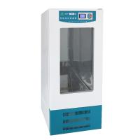 SANFA SHP-500 Biochemical Incubator 500L$ 2073.00
-
 SANFA SHP-400 Biochemical Incubator 400L$ 1624.00
-
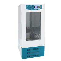 SANFA SHP-300 Biochemical Incubator 300L$ 1082.00
-
-

-


- 1SANFA SHP-E series biochemistry cultivating box instruction manual
- 2SANFA SYQX-II anaerobic incubator instruction manual
- 3NOBOTECH NPT-PH101/PH106 Waterproof Pen pH/ORP Meter Instruction Manual
- 4NOBOTECH NPT-CD501/CD506 Waterproof Pen Type Conductivity detector /TDS Instruction Manual
- 5NOBOTECH NPT-DO601 Pen Dissolved Oxygen Detector Instruction Manual
- 6NOBOTECH NPT-CLOZ801 Pen type residual chlorine/ozone detector instruction manual
- 7NOBOTECH PH-1186 Industrial Online PH/ORP Meter Instruction Manual
- 8NOBOTECH DOZ-7600 Online Water Ozone Detector Instruction Manual
- 9NOBOTECH CD-5000 Industrial Online Conductivity /TDS Instruction Manual
- 10NOBOTECH DO-6800 Industrial Online Dissolved Oxygen Instrument Instruction Manual