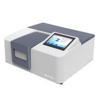
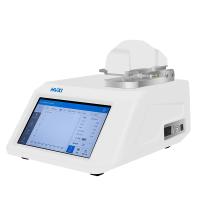
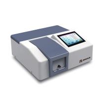
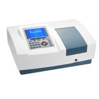
Introduction to UV Spectrophotometer
The instrument has a built-in microcomputer, and there are simple operation keys and LCD display windows on the panel, which can be operated independently without PC control.
The instrument optical system has the advantage of low stray light.
The instrument has the stability and reliability of long-term work.
The sample chamber is spacious and can be equipped with a variety of accessories. For example, configure a micro-sample rack and a micro-sample cell to measure and analyze micro-sample.
The instrument is equipped with a standard RS-232C communication port and a parallel printing port.
Through the Chengguang application software and the ordinary personal computer equipped with Microsoft Windows system on-line, the experimental test and data processing are carried out, which makes the analysis work more satisfying.
Principle of UV Spectrophotometer
1. The principle of the optical system. The optical system adopts a grating self-aligning dispersion system and a single-beam structured optical path. The continuous radiation emitted by a halogen lamp or a neon lamp passes through a cut-off filter to form a reflector. The slit of the color filter is located in the focal plane of the condenser mirror and the collimator mirror in the monochromator. Therefore, the compound light entering the monochromator is reflected by the plane reflector and collimated by the collimating mirror to become parallel light and shoot to the grating of the dispersion element. Due to the diffraction effect of the grating, the parallel light forms continuous monochromatic arrays uniformly arranged in a certain order. The color spectrum is reflected back on the collimating mirror. Since the light exit slit of the instrument is set on the focal plane of the collimating mirror, the homogeneous spectrum dispersed from the grating is concentrated on the exiting slit after passing through the collimating mirror. As the selected wavelength changes, the grating angle also changes. Therefore, on the fixed exit slit, select the monochromatic light with a specified bandwidth, focus it on the center of the sample to be measured in the sample chamber through the condenser lens, and transmit the light absorbed by the sample to the cathode surface of the phototube through the light gate, where the protection Glass is provided to prevent dust from entering the monochromator.
2. Optical path adjustment
1. The optical path deviation of the type UV spectrometer can be adjusted according to the following methods. When the wavelength scale indicator is set at 550nm, there should be half and half yellow and white spots on the condenser mirror in the lamp room of the light source. Otherwise, the cut-off filter should be loosened and positioned on the frame. Screw, change the rotation position of the cut-off filter group, so that the center of the condenser is half yellow and white, and then tighten the set screw.
2. Put a piece of white paper in the sample chamber, observe the light spot facing the light path, and adjust the wavelength knob. When the wavelength scale indicates 580nm, the light spot should be yellow. Otherwise, you can loosen a positioning screw on the wavelength scale plate to change The position of the wavelength dial panel. When the emitted light is yellow, set the wavelength dial indicator to 580nm and tighten the 3 positioning screws.
3. In order to make the exit spot of the monochromator pass through the sample and hit the photocell correctly, loosen the 4 screws under the monochromator, and change the position of the entire optical system appropriately. When the sample groove is placed in the "sample" position, the spot will Pass through the center of the sample slot and make the digital display read the highest, then tighten the 4 screws.